Some
Clarifications
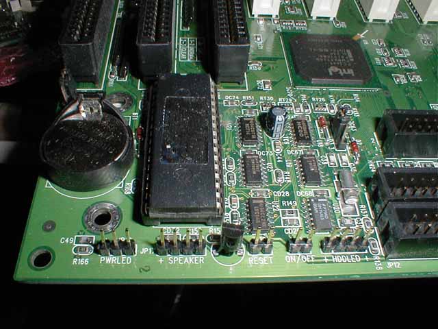
Here is a shot of a standard motherboard front panel connectors. Rob’s idea of using a standard IDE or floppy connector won’t work with this board, because the spacing is correct for each unit (hd LED, pwr, etc.) but the spacing isn’t the same between the units. I tried. You’ll need some standard (2.54mm/0.100 inch) motherboard connectors. Some CD-ROM to sound card connectors should work for connectors, if you can find them cheap enough. I can get them for $0.69, but I’ve seen places charge $5.00 for them.
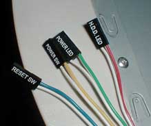
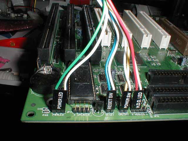
Here is a shot of a standard motherboard front panel connectors with a standard case’s motherboard connectors plugged into it. You might notice that the power LED connector is a 3-place connector with the center place devoid of wire. This is not the case for every motherboard. The little connectors inside the plug are easily moved from one place to the other within the plug.
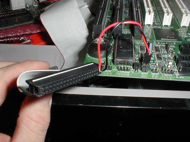
Here is a shot of what the finished connector should look like. (Here is a bigger shot of the same thing. I’m trying to be considerate of you modem folks.) I threw away my Dell connector, so this is a plain IDE connector. This is just an illustration. I just installed one motherboard connector (cuz it’s all I have left) and stuck it on the motherboard to illustrate. It isn’t in the correct place in the ribbon connector. To determine where to stick the wires in the Dell connector, go here. You’ll need some way to connect the wires to the connector. I just stuck these in. That might work. You might be able to tin (coat with solder) the bare wires and just stick them in the appropriate slot in the connector. …then tape it up so they don’t pull out.