*** Originally posted July 2006 ***
| The Background: |
 |
The 5W Epiphone Valve Junior has certainly created a stir among devotees of tube-based guitar amplifiers. This little gem has quickly established a cult following, since it offers genuine class A tube amp vibe for a ridiculously low price ($140 for the combo, $100 for the newer head model). And you can pick up used examples of the combo version in good condition on eBay for well under $100 (I got mine for $92).
But as good as the original combo version of the VJr was, it had some shortcomings, too--completely understandable in an amp this inexpensive. Consequently, a number of ambitious and knowledgeable VJr owners have developed various modifications to the amp to improve upon these various minor deficiencies. These modifications are covered in much more detail on various other websites (see the links below). Being a total "noob" with respect to electronics, I won't endeavor to go into the technical depth they do. After doing as much reading as I could on the subject and being impressed by the fact that these mods were both cheap and relatively simple to do, I put my own Valve Junior mod plan together. The purpose of this webapage is to document, in words and photos, what I did and how it turned out. While I hope this information can be of use to other VJr owners who want to improve their amp's performance, there is no substitute for "doing your homework", especially if (like me) you're new to this stuff. These are the websites where I found all of the information that I based my own modification plan upon, and I strongly suggest that you check them out:
Erik Miller's VJr Mods at Euthymia Electronics
After I purchased my Valve Junior and started playing through it, the aforementioned deficiencies became fairly obvious. First and foremost is it's propensity to hum. In fact, the amp hums in two completely different ways--a low-level background hum that is independent of the amp's volume setting, and a more obnoxious "buzzy" hum that builds as the volume is increased. The causes of these hums are a combination of sloppy grounding practices, inadequate power filtration, some less-than-optimal trace layout on the PCB, and the use of AC power to heat the tube filaments. On the VJr combo I bought, the ambient hum was quite subtle, but the volume-dependent buzz was pretty bad with the volume knob up past 2 PM or so. I found several different mods that were designed to reduce either or both of these hum types, ranging from very simple to a bit more involved. The good news is that none of them are expensive, so I elected to do several of them and see how much improvement I could get. (NOTE: These hum deficiencies were addressed in the head version of the VJr, and I understand new production of the combo incorporates the fixes, too.)
A second shortcoming that I noticed in my VJr was a rather dull tone, lacking "top end". I found myself maxing out the treble tone controls on all of my guitars when I played though it. Though the mod sites listed above tended to go after the hum issues as the primary improvement need, all of them made changes that boosted the amp's top end to some extent, as well, so I was obviously not alone in my opinion. Since I don't often crank the volume up into the range where the buzzy hum gets really bad, I actually considered this need for more brightness to be my first priority. I swapped the stock Sovtek tubes for JJ's from Eurotubes.com, and though the amp's tone improved and brightened slightly, the improvement was nowhere near what I was looking for.
In addition to the above two issues, a number of other mods were described at these various websites, mostly falling into the category of enhancements to the VJr's intentionally sparse feature set. These included things like adding a high gain switch, an additional 8 ohm output jack, or installing a small light bulb to act as a signal attenuator. However, I had no personal need for or interest in any of these, and opted to pass on implementing them.
| The Plan: |
To deal with the hum issues, I decided to make the following four modifications:
- Improve grounding on the PCB by adding a jumper wire between two of the traces. This corrects a grounding design deficiency.
- Replace the stock input jack with a nylon insulated jack, to isolate it from the chassis.
- Add a larger filtering capacitor (100uf/450V) to the main high voltage supply stage, to supplement the smaller stock caps.
- Convert the voltage supply to the tube heater filaments from AC to DC, requiring the addition of a small bridge rectifier and 1000uf/25V capacitor.
To improve the brightness characteristics of the amp, I opted for two additional mods:
- Boost the amount of input signal going to the preamp stage and reduce the signal bleed to ground by changing two resistors on the PCB. Specifically, R1 is increased to 1M and R2 is lowered to 22K. These resistor changes also cause a net increase in the input impedance of the amp, which has the effect of boosting the highs a bit.
- Add a switchable tone capacitor to an open position on the PCB (C3), i.e. install a "brightness switch".
Once I decided what to do, the next task was to accumulate the parts I needed. The expert's links above gave me the basics of what I needed, but being totally inexperienced in electronics, knowing exactly what to get and where to get it was more of a challenge. After running around to a couple of local stores in search of these components and having very little luck, I ended up ordering everything online from Mouser.com. Not only do these guys have pretty much every electrical component known to mankind, but they also don't have a minimum order size, which is a nice plus! To make it easier for any of you amateur modders who want to give this stuff a try, HERE is a copy of my VJr mod "bill of materials" in PDF format. It includes all the Mouser and manufacturer part numbers to make ordering easy. Note that I bought three different tone capacitor sizes, plus a couple of extra resistors to have on hand. The total before shipping came to a bit over $22. Cheap!
| The Execution: |
Once the parts arrived, I got down to the business of installing them. Let me say right up front that I had help. Yours truly has never soldered a thing in his life, and this didn't seem like a good time to learn. Fortunately, we have a couple of very accomplished electronics techs where I work, and they were good enough to help me out during a couple of my lunch hours. With their able assistance, the six modifications described above were completed in short order.
I should mention that in the course of installing these six mods, it was necessary to drill two new holes through the amp's metal chassis. One was a small hole through the bottom to accomodate the mounting bolt for the bridge rectifier, and a second, larger hole was required in the front panel for the new brightness toggle switch.
So let's see what these modifications look like....
Here's a simple schematic of the Valve Jr's PCB, showing the mods that were done on the board itself:
 |
Here's a photo of a portion of the PCB, showing some of the installed mods, circled in red and numbered:
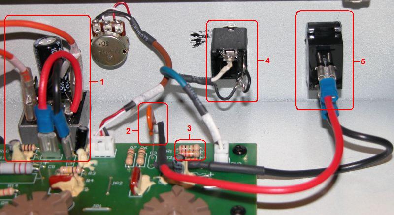 |
The mods shown above are as follows:
- The bridge rectifier and 1000uf/25V capacitor. The orange wires formerly connected to terminals T5 and T6 on the PCB, but now connect to the rectifier, whose + and - terminals now connect to those board terminals. The capacitor is soldered across the + and - terminals of the rectifier. IMPORTANT: These electrolytic caps are polar, so the positive side must go to the positive terminal of the rectifier, and the negative side to the negative terminal. If wired backwards, they can literally explode when energized!
- Ceramic 68pf tone capacitor, soldered to one of the two open C3 terminals on the PCB (ceramic caps are not polar, so it doesn't matter which end is soldered to the PCB). The other end is wired to the toggle switch in the panel face (#5), and the other side of the switch is wired back to the second C3 terminal.
- The two new resistors (R1 = 1M and R2 = 22K) that were substituted for the stock resistors.
- The back of the new nylon insulated input jack.
- The back of the "brightness switch" toggle.
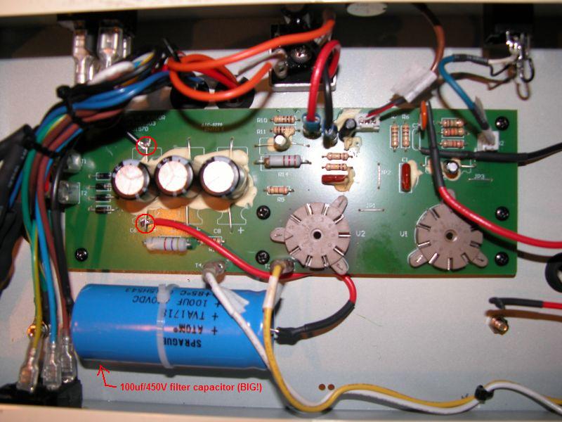
Here's a different view of the PCB, showing the big 100uf/450V filter capacitor, which is wired in parallel with the smaller filter caps on the board. The connection points are circled in red. The capacitor is lashed down to the chassis with a wire tie fastened to an adhesive anchor pad. Again, you MUST pay attention to the capacitor's polarity when making these connections!
 |
And here's a photo, courtesy of Dennis Cronin's web page, showing where the grounding jumper is installed on the back of the PCB:
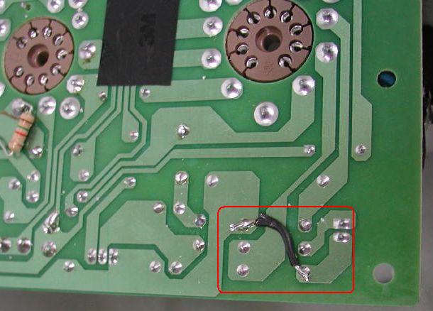 |
Some comments on the individual modifications, for additional clarification and guidance:
- Bridge rectifier installation - Because the AC to DC conversion generates heat, the experts strongly suggest that the rectifier be bolted firmly to the chassis to facilitate cooling by heat transfer. I went a step further by smearing a little thermal paste on the bottom of the rectifier block, to give better surface contact. The connections to the rectifier are pretty easy to figure out, but I've posted a diagram I found online HERE, for reference.
- Tone caps - Because I'd read comments that lead me to believe that a 50pf cap might give too little brightness boost and a 100pf cap too much, I opted to install the 68pf cap. But I bought one of each size so that I could go bigger or smaller, depending upon how the 68pf cap sounded to me.
- Nylon insulated input jack - In addition to soldering the hot and ground leads to the jack's tip and sleeve terminals, respectively, we also soldered a short jumper between the sleeve and tip shunt terminals. The original input jack was wired this way, so I did the same thing with the new one. Don't know if it's really necessary, but it seems to work fine. HERE is a diagram that shows the terminal layout of the Switchcraft N112A input jack.
Lastly, here's the finished product, all reassembled and ready to run. The only giveaway that the amp has been modded is the brightness toggle at the left side of the front panel:
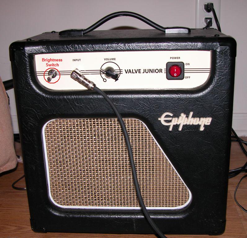 |
| The Results: |
And what did this all accomplish, you ask?
Well, a whole bunch, actually. The ambient hum is completely gone, to my ear. The volume-dependent buzz is much reduced, and far less "buzzy" in character now. More of a true hum, and no worse than I get with my Peavey Delta Blues cranked up. I don't even really notice it until the volume is at 3/4, and I rarely play there, anyway! So the four hum fixes have definitely done their job.
As for brightening the tone, mission accomplished there, too. The resistor changes made a difference, and the new brightness switch takes it the rest of the way there. With the switch on to engage the tone cap, the top-end brightens up nicely. Makes a noticeable difference with both single poles & humbuckers. I like it so much I'll probably just leave it "on" most of the time. And if I ever decide I'd like a bit more brightness, I can always go back into the amp and replace the 68pf tone cap with a 100pf version.
Here's a couple of audio clips recorded with my Strat and my Les Paul to show the effect. Each clip contains two pairs of recordings of the same short riff, with each pair using different pickup settings. Within each pair, the brightness switch is off for the first riff, then on for the second:
| Tone Cap Update: Since the original modifications were done, I've changed from the 68pf tone cap to a 100pf cap, mostly out of curiosity to hear how big a difference it would make. As expected, the brightness increase heard when flipping the toggle on is more pronounced, but not excessively so, in my opinion. Personally, I like having a little more high end on tap, and it's easy enough to roll off the treble knobs on the guitar if it sounds a little too bright in a given situation. I've posted new comparison audio clips for both my Strat and my Les Paul. As before, the brightness switch is off for the first riff, and on for the second. |
So there you have it, folks. If you have any questions, feel free to drop me a line by e-mail, per the address link below. And if you're contemplating trying some of these mods on your own Valve Junior, just keep this in mind--if an electronics ignoramus like me can do it (with some soldering help!), anyone can! Just take the proper precautions to work safely around these high voltage components! Good luck & be careful!!
JAN. 2008 UPDATE: After enjoying my improved Valve Junior for well over a year, I decided to make some further upgrades. Here's the rundown on the three additional improvements that I recently completed:
Speaker Upgrade - Though the stock speaker was by no means bad, I wanted to get a bit more sparkle and clarity than it offered. I swapped in a Jensen C8R that I picked up at TubeDepot.com for a mere $28. It gives the VJr a nice Fendery top-end that really makes clean single coil tones come alive. |
Bob Matthews, a.k.a. "Duh Voodoo Man"
Last Updated January 22, 2008
Questions or comments? E-mail me at THIS LINK
And please visit Duh Voodoo Man's HOME PAGE!